
Dynamic Rate Switching (DRS)
. . . .
Dynamic Rate Switching (DRS)
- As client station radios move away from an access point, they will shift down to lower-bandwidth capabilities by using a process known as dynamic rate switching (DRS).
- Access points can support multiple data rates depending on the spread spectrum technology used by the AP radio.
- For example, a legacy 802.11b radio supports data rates of 11, 5.5, 2, and 1 Mbps.
- Data rate transmissions between the access point and the client stations will shift down or up depending on the quality of the signal between the two radios, as pictured in Figure 12.16.
- There is a correlation between signal quality and distance from the AP.
- As mobile client stations move further away from an access point, both the AP and the client will shift down to lower rates that require a less complex modulation coding scheme (MCS).
- For example, transmissions between two 802.11b radios may be at 11Mbps at 30 feet but 2 Mbps at 100 feet.

Figure 12.16 Dynamic rate switching
- DRS is also referred to as dynamic rate shifting, adaptive rate selection, and automatic rate selection.
- All these terms refer to a method of speed fallback on a Wi-Fi radio receiver (Rx) as the incoming signal strength and quality from the transmitting Wi-Fi radio decreases.
- The objective of DRS is upshifting and downshifting for rate optimization and improved performance.
- The lower data rates will have larger concentric zones of coverage than the higher data rates, as Figure 12.17 shows.
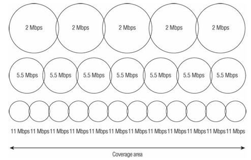
Figure 12.17 Data rate coverage zones
- The thresholds used for dynamic rate switching are proprietary and
are defined by 802.11 radio manufacturers. - Most vendors base DRS on:
- receive signal strength indicator (RSSI) thresholds
- packet error rates
- retransmissions
- RSSI metrics are usually based on signal strength and signal quality.
- In other words, a station might shift up or down between data rates based on received signal strength in dBm and possibly on a signal-to-noise ratio (SNR) value.
- Because vendors implement DRS differently, you may have two different vendor client radios at the same location, while one is communicating with the access point at 5.5 Mbps and the other is communicating at 1 Mbps.
- For example, one vendor might shift down from data rate 11 Mbps to 5 Mbps at –75 dBm, whereas another vendor might shift between the same two rates at –78 dBm.
- Keep in mind that DRS works with all 802.11 physical layers (PHYs).
For example, the same shifting of rates will also occur with 802/11a/g radios shifting between 54, 48, 36, 24, 18, 12, 9, and 6 Mbps data rates.
As a result, there is a correlation between signal quality and distance from the AP. - Please understand that all WLAN radios use dynamic rate switching. As already mentioned, client radios shift down to lower data rates if there is a weaker received signal from the AP. The radio within an access point also uses dynamic rate switching.
- Based on the incoming received signal strength from a client, an access point radio will shift data rates for the downstream transmission back to the client radio.
- It is often a recommend practice to turn off the two lowest data rates of 1 and 2 Mbps when designing a 2.4 GHz 802.11b/g/n network.
A WLAN network administrator might want to consider disabling the two lowest rates on a 2.4 GHz access point for three reasons:- sticky client roaming problems
- medium contention
- the hidden node problem.
- In Figure 12.18, you will see that multiple client stations are in the 1 Mbps zone and only one lone client is in the 11 Mbps zone.
- Remember that wireless is a half-duplex medium and only one radio can transmit in the medium at a time.
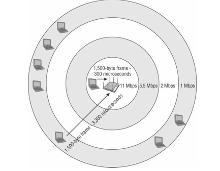
Frame 12.18 Frame transmission time
- When 802.11 radios transmit at very low data rates such as 1 Mbps and 2 Mbps, effectively they cause medium-contention overhead for higher data rate transmitters due to the long wait time.
- All radios access the medium in a pseudorandom fashion, as defined by CSMA/CA.
- A radio transmitting a 1,500-byte data frame at 11 Mbps might occupy the medium for 300 microseconds. Another radio transmitting at 1 Mbps per second may take 3,300 microseconds to deliver that same 1,500 bytes.
- Radios transmitting at slower data rates will occupy the medium much longer, whereas faster radios have to wait.
- If multiple radios get on the outer cell edges and transmit at slower rates consistently, the perceived throughput for the radios transmitting at higher rates is much slower because of having to wait for slower transmissions to finish.
- For this reason, too many radios on outer 1 and 2 Mbps cells can adversely affect
throughput. - Most vendors use proprietary airtime fairness mechanisms only for downstream
transmissions from an AP to an associated client. - Airtime fairness mechanisms are normally used for prioritizing the higher data rate downstream transmissions from an access point over the lower data rate downstream transmissions from an access point to client stations.
- If airtime fairness mechanisms are implemented properly, disabling the lower data rates on a 2.4 GHz access point may not be required.
- However, another reason to consider turning off the lower data rates is the hidden node problem
- Turning off the lower data rates is also a common practice to limit cell size when designing high-density WLANs.
Reference:
Coleman, David D.,Westcott, David A. CWNA: Certified Wireless Network Administrator Official Study Guide: Exam CWNA-106 Wiley.
Coleman, David D.,Westcott, David A. CWNA: Certified Wireless Network Administrator Official Study Guide: Exam CWNA-106 Wiley.
|
|