
Lightning arrestors and grounding rods/wires
. . . .
Lightning arrestors
- The purpose of a lightning arrestor is to redirect (shunt) transient currents caused by nearby lightning strikes or ambient static away from your electronic equipment and into the ground.
- Lightning arrestors are used to protect electronic equipment from the sudden surge of power that a nearby lightning strike or static buildup can cause.
- Lightning arrestors are not capable of protecting against a direct lightning strike.
- Lightning arrestors can typically protect against surges of up to 5,000 amperes at up to 50 volts.
- The IEEE specifies that lightning arrestors should be capable of redirecting the transient current in less than 8 microseconds.
- Most lightning arrestors are capable of doing it in less than 2 microseconds.
- The lightning arrestor is installed between the transceiver and the antenna.
- Any devices that are installed between the lightning arrestor and the antenna will not be protected by the lightning arrestor.
- Therefore, the lightning arrestor is typically placed closer to the antenna, with all other communications devices (amplifiers, attenuators, etc.) installed between the lightning arrestor and the transceiver.
- Figure 4.22 shows a properly grounded radio, cabling, and antenna.
- After a lightning arrestor has performed its job by protecting the equipment from an electrical surge, it will have to be replaced, or it may have a replaceable gas discharge tube (like a fuse).
- Most installations place the lightning arrestor at the egress to the building. Cable grounding kits can be installed near the antenna and at every 100 feet.
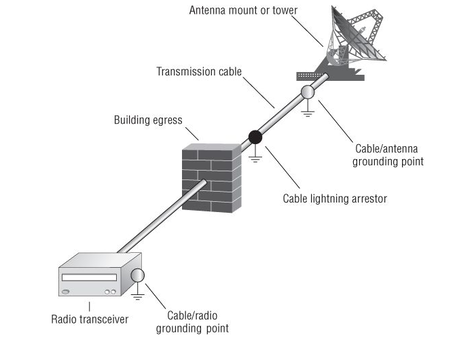
Figure 4.22 Installation of lightning protection equipment
Ground rods and wires
- When lightning strikes an object, it is looking for the path of least resistance, or more specifically, the path of least impedance.
- A grounding system, which is made up of a grounding rod and wires, provides a low-impedance path to the ground.
- This low-impedance path is installed to encourage the lightning to travel through it instead of through your expensive electronic equipment.
- Grounding rods and wires are also used to create what is referred to as a common ground.
- One way of creating a common ground is to drive a copper rod into the ground and connect your electrical and electronic equipment to this rod by using wires or straps (grounding wires).
- The grounding rod should be at least 6 feet long and should be fully driven into the ground, leaving enough of the rod accessible to attach the ground wires to it.
- By creating a common ground, you have created a path of least impedance for all of your equipment should lightning cause an electrical surge.
- On tower structures, a grounding rod should be placed off of each leg with a No. 2 tinned copper wire.
- These connections should be exothermically welded to the tower legs.
- A No. 2 tinned copper wire should also form a ring around the grounding rods.
- The dashed lines are No. 2 tinned copper wire and the circles are grounding rods.
- Ice bridges and building grounds should also be bonded to this ring to provide equal grounding potentials.
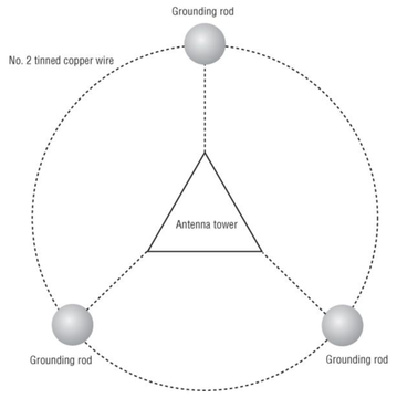
Grounding ring
Reference:
Coleman, David D.,Westcott, David A. CWNA: Certified Wireless Network Administrator Official Study Guide: Exam CWNA-106 Wiley.
Coleman, David D.,Westcott, David A. CWNA: Certified Wireless Network Administrator Official Study Guide: Exam CWNA-106 Wiley.
|
|