Line of Sight and Fresnel zone issues
. . . .
Visual Line of Sight
- When light travels from one point to another, it travels across what is perceived to be an unobstructed straight line, known as the visual line of sight (LOS).
- For all intents and purposes, it is a straight line, but because of the possibility of light refraction, diffraction, and reflection, there is a slight chance that it is not.
- When it comes to RF communications, visual LOS has no bearing on whether the RF transmission is successful.
RF Line of Sight
- Point-to-point RF communication also needs to have an unobstructed visual LOS between the two antennas.
- The first step for installing a point-to-point system is to make sure that, from the installation point of one of the antennas, you have a clear direct path to the other antenna.
- For RF communications to work properly, an additional area around the visual LOS needs to remain clear of obstacles and obstructions.
- This area around the visual LOS is known as the Fresnel zone and is often referred to as RF line of sight.
Fresnel Zone
- The Fresnel zone exists in all RF communications; however, it is in outdoor point-to-point communications where it can cause the most problems.
- Indoor environments have so many walls and other obstacles where there is already so much reflection, refraction, diffraction, and scattering that the Fresnel zone is not likely to play a big part in the success or failure of the link.
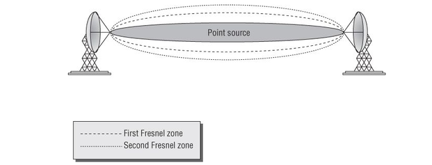
- The Fresnel zone is an imaginary, elongated (longer, especially unusually so in relation to its width), american football-shaped area that surrounds the path of the visual LOS between two point-to-point antennas.
- The Fresnel zone exists below, to the sides, and above the visual LOS.
Theoretically, there are an infinite number of Fresnel zones, or concentric ellipsoids (the football shape), that surround the visual LOS.
When highly directional antennas are used, the beamwidth of the signal is smaller, causing a more focused signal to be transmitted.
Many people think that a smaller beamwidth would decrease the size of the Fresnel zone. This is not the case.
The size of the Fresnel zone is a function of the frequency being used and the distance of the link.
Since the only variables in the formula are frequency and distance, the size of the Fresnel zone will be the same regardless of the antenna type or beamwidth.
Factors that affect the Fresnel zone
In Phase / Out of Phase
If an RF signal of the same frequency but out of phase with the primary signal intersects the primary signal, the out-of-phase signal will cause degradation or even cancellation of the primary signal.
The first Fresnel zone is technically the area around the point source, where the waves are in phase with the point source signal.
One of the ways that an out-of-phase signal can intercept the primary signal is by reflection.
First Fresnel zone
The radius of the first Fresnel zone, at the midpoint between the two antennas is the point where the Fresnel zone is the largest.
This is the optimal clearance that you want along the signal path.
If the first Fresnel zone becomes even partly obstructed, the obstruction will negatively influence the integrity of the RF communication.
In addition to the obvious reflection and scattering that can occur if there are obstructions between the two antennas, the RF signal can be diffracted or bent as it passes an obstruction of the Fresnel zone.
This diffraction of the signal decreases the amount of RF energy that is received by the antenna and may even cause the communications link to fail.
Figure 4.18 illustrates a link that is 1 mile long.
- The closest ellipsoid is known as the first Fresnel zone.
- The next one is the second Fresnel zone, and so on.
- The subsequent Fresnel zones have little effect on communications.
When highly directional antennas are used, the beamwidth of the signal is smaller, causing a more focused signal to be transmitted.
Many people think that a smaller beamwidth would decrease the size of the Fresnel zone. This is not the case.
The size of the Fresnel zone is a function of the frequency being used and the distance of the link.
Since the only variables in the formula are frequency and distance, the size of the Fresnel zone will be the same regardless of the antenna type or beamwidth.
Factors that affect the Fresnel zone
- The typical obstacles that you are likely to encounter outdoors are trees and buildings.
- A common scenario is the deployment of point-to-point links in an urban city environment.
- Very often building-to-building links must be shot between other buildings.
In these situations, other buildings have the potential of impeding the side radiuses of the Fresnel zone.
- It is important to periodically visually check your link to make sure that trees have not grown into the Fresnel zone or that buildings have not been constructed that encroach into the Fresnel zone.
- Because of the curvature of the earth, you will need to raise the antennas even higher to compensate for the earth’s bulge.
- You should also be cautious of metal surfaces or calm water along the Fresnel zone.
In Phase / Out of Phase
- All of the odd-numbered Fresnel zones are in phase with the point source signal.
- All of the even-numbered Fresnel zones are out of phase.
If an RF signal of the same frequency but out of phase with the primary signal intersects the primary signal, the out-of-phase signal will cause degradation or even cancellation of the primary signal.
The first Fresnel zone is technically the area around the point source, where the waves are in phase with the point source signal.
One of the ways that an out-of-phase signal can intercept the primary signal is by reflection.
First Fresnel zone
The radius of the first Fresnel zone, at the midpoint between the two antennas is the point where the Fresnel zone is the largest.
This is the optimal clearance that you want along the signal path.
If the first Fresnel zone becomes even partly obstructed, the obstruction will negatively influence the integrity of the RF communication.
In addition to the obvious reflection and scattering that can occur if there are obstructions between the two antennas, the RF signal can be diffracted or bent as it passes an obstruction of the Fresnel zone.
This diffraction of the signal decreases the amount of RF energy that is received by the antenna and may even cause the communications link to fail.
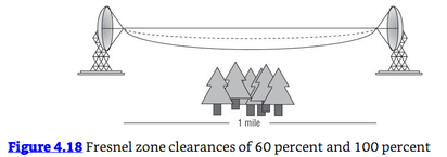
Figure 4.18 illustrates a link that is 1 mile long.
- The top solid line is a straight line from the center of one antenna to the other.
- The dotted line shows 60 percent of the bottom half of the first Fresnel zone.
- The bottom solid line shows the bottom half of the first Fresnel zone.
- The trees are potential obstructions along the path.
Under no circumstances should you allow any object or objects to encroach more than 40 percent into the first Fresnel zone of an outdoor point-to-point bridge link. Anything more than 40 percent is likely to make the communications link unreliable.
Even less than 40 percent obstruction is likely to impair the performance of the link.
It is recommended that you do not allow any obstruction of the first Fresnel zone.
Particularly in wooded areas where the growth of trees may obstruct the Fresnel zone in the future.
Second Fresnel zone
It is important to consider the second Fresnel zone when evaluating point-to-point communications.
The second Fresnel zone is then the area beyond the first Fresnel zone, where the waves are out of phase with the point source signal.
Although this is not a common occurrence, the second Fresnel zone should be considered when planning or troubleshooting the connection, especially in flat, arid terrain, like a desert.
If the height of the antennas and the layout of the geography are such that the RF signal from the second Fresnel zone is reflected toward the receiving antenna, it can cause degradation of the link.
Earth Bulge
- When you are installing long-distance point-to-point RF communications, another variable that must be considered is the curvature of the earth, also known as the earth bulge.
- Because the landscape varies throughout the world, it is impossible to specify an exact distance for when the curvature of the earth will affect a communications link.
- The recommendation is that if the antennas are more than 7 miles away from each other. You should take into consideration the earth bulge, because after 7 miles, the earth itself begins to impede on the Fresnel zone.
Reference:
Coleman, David D.,Westcott, David A. CWNA: Certified Wireless Network Administrator Official Study Guide: Exam CWNA-106 Wiley.
Coleman, David D.,Westcott, David A. CWNA: Certified Wireless Network Administrator Official Study Guide: Exam CWNA-106 Wiley.
|
|


