
System Operating Margin (SOM), fade margin and link budget
. . . .
Link Budget
A link budget is the sum of all the planned and expected gains and losses:
Link budget calculations include:
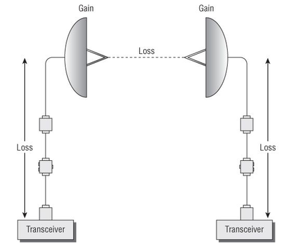
Point-to-point wireless bridge link and shows that loss occurs as the signal moves through various RF components as well as the signal loss caused by FSPL.
A link budget is the sum of all the planned and expected gains and losses:
- From the transmitting radio
- Through the RF medium
- To the receiver radio
Link budget calculations include:
- Original transmit gain
- Passive antenna gain
- Active gain from RF amplifiers
- Attenuators
- FSPL
- Insertion loss
- Any hardware device installed in a radio system adds a certain amount of signal attenuation called insertion loss
- Cabling is rated for dB loss per 100 feet
- Connectors typically add about 0.5 dB of insertion loss
Point-to-point wireless bridge link and shows that loss occurs as the signal moves through various RF components as well as the signal loss caused by FSPL.
Link Budget
The two antennas are 10 kilometers apart, and the original transmission is + 10 dBm. Notice the amount of insertion loss caused by each RF component, such as the cabling and the lightning arrestors. The antennas passively amplify the signal, and the signal attenuates as it travels through free space. The final received signal at the receiver end of the bridge link is –65.5 dBm.
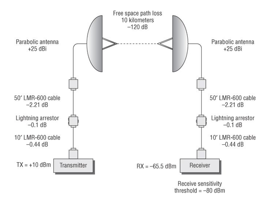
Link Budget Example
Now, let’s assume that the receive sensitivity threshold of the receiver radio is –80 dBm.
Any signal received with amplitude above –80 dBm can be understood by the receiver radio, whereas any amplitude below –80 dBm cannot be understood.
The link budget calculations determined that the final received signal is –65.5 dBm, which is well above the receive sensitivity threshold of –80 dBm.
There is almost a 15 dB buffer between the final received signal and the receive sensitivity threshold.
The 15 dB buffer that was determined during link budget calculations is known as the fade margin.
Fade Margin
- Fade margin is a level of desired signal above what is required. You can think of fade margin as the buffer or margin of error for received signals that is used when designing and planning an RF system.
- If a receiver has a receive sensitivity of –80 dBm, a transmission will be successful as long as the signal received is greater than –80 dBm.
- The problem is that the signal being received fluctuates because of many outside influences such as interference and weather conditions.
- To accommodate for the fluctuation, it is a common practice to plan for a 10 dB to 25 dB buffer above the receive sensitivity threshold of a radio used in a bridge link.
- The 10 dB to 25 dB buffer above the receive sensitivity threshold is the fade margin.
- A fade margin of 10 dB is an absolute minimum.
- This would only be acceptable for links less than 3 miles or so.
- Up to 5 miles should have at least a 15 dB fade margin, and links greater than that should be higher.
- A fade margin of 25 dB is recommended for links greater than 5 miles.
- When deploying a WLAN indoors where high multipath or high noise floor conditions exist, the best practice is to plan for a fade margin of about 5 dB above the vendor’s recommended receive sensitivity amplitude.
- For example, a –70 dBm or stronger signal falls above the RSSI threshold for the higher data rates for most WLAN vendor radios.
- During the indoor site survey, RF measurements of –70 dBm will often be used to determine coverage areas for higher data rates.
- In a noisy environment, RF measurements of –65 dBm utilizing a 5 dB fade margin is a recommended best practice.
System Operating Margin (SOM)
- After the RF link has been installed, it is important to measure the link to see how much buffer or padding there actually is.
- This functional measurement is known as the system operating margin (SOM).
- The SOM is the difference between the actual received signal and the signal necessary for reliable communications.
Reference:
Coleman, David D.,Westcott, David A. CWNA: Certified Wireless Network Administrator Official Study Guide: Exam CWNA-106 Wiley.
Coleman, David D.,Westcott, David A. CWNA: Certified Wireless Network Administrator Official Study Guide: Exam CWNA-106 Wiley.
|
|