
VSWR
. . . .
VSWR
What is VSWR?
Voltage Standing Wave Ratio (VSWR) is the measurement of change in impedance to an AC signal.When a transmitter generates the AC radio signal, the signal travels along a cable to the antenna. Some of this signal is reflected back to the transmitter because of an occurrence known as an impedance mismatch.
VSWR is a numerical relationship between the measurement of the maximum voltage generated by the transmitter and the measurement of the the minimum voltage that is received by the antenna.
VSWR is a ratio of impedance mismatch.
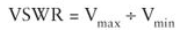
VSRW Formula
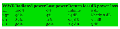
The larger the VSWR, the more voltage is being reflected back to the transmitter, causing a decrease in power of the signal that is supposed to be transmitted.
Why do we need VSWR?
When there is an impedance mismatch or variations between devices (transmitter, cable, antenna) in a RF system. We can measure the signal loss caused by using VSWR.
What is impedance?
Impedance is a value of Ohms of electrical resistance to an AC signal.
What is an impedance mismatch?
In an RF communication system you have the transmitter, the antenna and the cabling connecting the transmitter and the antenna together.
Each three of these components will have a rating of how many Ohms they can handle.
Mismatches may occur anywhere along the signal path but usually occur due to sudden impedance changes between the radio transmitter and cable and between the cable and the antenna
Examples scenarios:
- Matched Impedance
When the transmitter generates a signal with 50Ohms of energy it flows through cabling which is also rated at 50Ohms, then reaches the antenna which is also rated at 50Ohms. The antenna will radiate the energy at 50Ohms and the impedance is equal throughout the RF system. - Mismatched Impedance
When the transmitter generates a signal with 50Omhs of energy it flows through cabling which is also rated at 50Ohms, then reaches the antenna but this time the antenna is rated at 25Ohms. The antenna will radiate the energy at 25Ohms of energy and the other 25ohms will be reflected back to the transmitter causing loss on the RF system.
What is a standing wave?
A standing wave is a combination of a wave that is being transmitted and (due to an impedance mismatch) the reflected wave that is coming back toward the transmitter due to an impedance mismatch. It is called a standing wave because the combined wave is stopping the wave from moving.
See the graphic below:
The wave is oscillating from the transmitter. Once the wave reaches the point where the impedance mismatch occurs, the oscillation becomes a standing wave.
Transient Standing Wave
Visualizing RF Standing Waves
An article including a YouTube video by Hackaday can be found at http://hackaday.com/2015/08/06/visualizing-rf-standing-waves/.
It gives a great explanation and the gentleman narrating the video has some special RF detector probing equipment which really hammers home what is happening when a standing wave occurs.
Reference:
Coleman, David D.,Westcott, David A. CWNA: Certified Wireless Network Administrator Official Study Guide: Exam CWNA-106 Wiley.
https://en.wikipedia.org/wiki/Standing_wave
http://hackaday.com/2015/08/06/visualizing-rf-standing-waves/
Coleman, David D.,Westcott, David A. CWNA: Certified Wireless Network Administrator Official Study Guide: Exam CWNA-106 Wiley.
https://en.wikipedia.org/wiki/Standing_wave
http://hackaday.com/2015/08/06/visualizing-rf-standing-waves/
|
|